
Selecting a crossed roller bearing is rarely a matter of picking a part number from a catalog. Because these bearings carry radial, axial and moment loads at the same time inside a single compact unit, the choice directly determines the rigidity, positioning accuracy and service life of the whole axis. This guide walks through the criteria engineers actually use — load analysis, stiffness, accuracy grade, mounting geometry, lubrication and operating environment — and shows how to turn those criteria into a specification a supplier can quote against. Whether you are designing a rotary table, a robot joint or a semiconductor handling stage, the same sequence of decisions applies.
In a crossed roller bearing, cylindrical rollers sit in a V-shaped raceway and are arranged alternately at 90 degrees to one another. Instead of the point contact found in ball bearings, the rollers make line contact with the raceway, and the 90-degree arrangement means each roller set resists load in a different direction. The result is a bearing that handles radial load, axial load and tilting moment simultaneously.
For machine designers this solves a practical problem. A conventional arrangement might need two angular contact bearings, a thrust bearing and a housing machined to hold them all in the right relationship. A single crossed roller bearing delivers comparable or better stiffness in a much shorter axial envelope. That is why the design shows up in rotary indexing tables, articulated robot arms, machine tool C-axes, radar pedestals, medical scanning gantries and wafer-handling robots — applications where a few micrometers of tilt or runout would compromise the process.
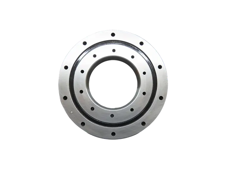
Start with the load case, not the catalog page. Establish the radial force, the axial force, and the moment arm acting on the bearing, including the inertia loads during acceleration and any off-center payload. Crossed roller bearings are usually rated with a dynamic radial capacity, a dynamic axial capacity and an allowable moment, and the limiting one is rarely the same in every application. A vertical rotary axis with an offset tool load is often moment-limited; a horizontal indexing table may be limited by radial load instead. Add a safety factor that reflects the consequences of failure and the certainty of the load estimate, and remember that shock and vibration from the machine itself belong in the calculation too.
...
For more detailed information regarding the selection guide for crossed roller bearings, please click here: https://www.prsbearings.com/news/crossed-roller/