
Crossed roller bearings are often specified when a single bearing must carry radial load, axial load, and tilting moment at the same time. Their cylindrical rollers are arranged at 90-degree intervals on one raceway, so alternating rollers take the load in different directions. That layout lets a compact bearing behave like two separate bearings fitted into one envelope. Understanding how the rollers share radial and axial forces helps engineers decide whether a crossed roller bearing is the right choice, and how to size it correctly. The sections below explain the load paths inside the bearing, the factors that limit capacity, and the design decisions that determine real-world performance.
A standard ball bearing handles radial load well but offers limited axial capability unless it is designed with a contact angle. A crossed roller bearing solves the problem geometrically rather than by adding a second row in a separate housing.
The rollers sit in a V-shaped raceway with a 90-degree included angle. Adjacent rollers are turned 90 degrees to each other, so the load line of one roller is perpendicular to the load line of its neighbour. Because each load line sits at roughly 45 degrees to the shaft axis, a roller can respond to both a radial and an axial force component at the same time. Under pure radial load, approximately half the rollers are loaded in compression along one diagonal; under axial load, the other set engages. This is why the bearing is described as capable of carrying loads in all directions with a single raceway pair.
Cylindrical rollers touch the raceway along a line, not at a point. Compared with a ball of similar envelope size, the contact area is far larger, so the stress per unit area is lower for a given load. The practical result is higher radial and axial stiffness and less elastic deflection under the same force. That stiffness is usually the reason a designer moves from a ball bearing to a crossed roller design in the first place.
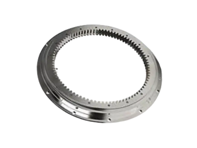
When a radial force is applied, the rollers whose load lines have a vertical component take the load and pass it into the housing wall. Several factors govern how evenly that happens:
Because the load zone in a crossed roller bearing is wider than in a comparable ball bearing, the bearing tolerates a slightly misaligned or deflecting support structure better, provided the misalignment stays within the manufacturer's stated limit.
...
For more detailed information on how crossed roller bearings accommodate radial and axial loads, please click here: https://www.prsbearings.com/news/axial-radial-load/