
Steel structures form the backbone of modern infrastructure, from high-rise buildings to industrial bridges. Understanding load-bearing capacity is critical for engineers, architects, and project owners who must ensure safety, longevity, and cost-efficiency. This article breaks down the engineering principles behind steel structure load capacity, including material behavior, design factors, and real-world applications. Whether you're specifying a new project or evaluating existing construction, the insights here will help you make informed decisions—and show how partners like MeiChen Steel deliver reliable solutions.
The load-bearing capacity of a steel structure is its maximum ability to resist applied forces without failure. This depends on three core elements: material strength, cross-sectional geometry, and structural stability. Steel is favored for its high strength-to-weight ratio, ductility, and uniformity compared to concrete or timber.
When a load is applied, steel experiences stress (force per unit area) and strain (deformation). The yield point—where steel begins to deform permanently—is a key design limit. For most structural steel grades like ASTM A36 or A992, yield strength ranges from 250 MPa to 345 MPa. Engineers design structures to remain below this limit under service loads, ensuring elastic behavior.
The shape of a steel member dramatically affects its load capacity. An I-beam, for example, has a high section modulus, meaning it resists bending efficiently. A wider flange increases stiffness without proportional weight gain. The section modulus (S) and moment of inertia (I) are calculated from geometry and used in bending stress formulas: σ = M / S.

Several interrelated factors determine the final capacity of a steel structure. Ignoring any can lead to underperformance or failure.
Design codes (AISC 360, Eurocode 3) use load and resistance factor design (LRFD) or allowable strength design (ASD). In LRFD, factored loads are compared with nominal strength reduced by a resistance factor (e.g., φ = 0.9 for bending). This accounts for material variability, modeling uncertainties, and construction tolerances.
A typical design sequence: 1) Determine required strength from load combinations. 2) Select trial member. 3) Check axial capacity (P_n), flexural capacity (M_n), shear capacity (V_n). 4) Verify combined stresses (biaxial bending + axial). 5) Check deflection serviceability (L/360 or tighter for sensitive structures).
For example, a W10x49 column in A992 steel (F_y = 345 MPa) with unbraced length 3 meters may have an axial capacity of approximately 1,800 kN in LRFD, considering slenderness ratio and buckling curve. Actual values require detailed computation—never rely on rules of thumb alone.
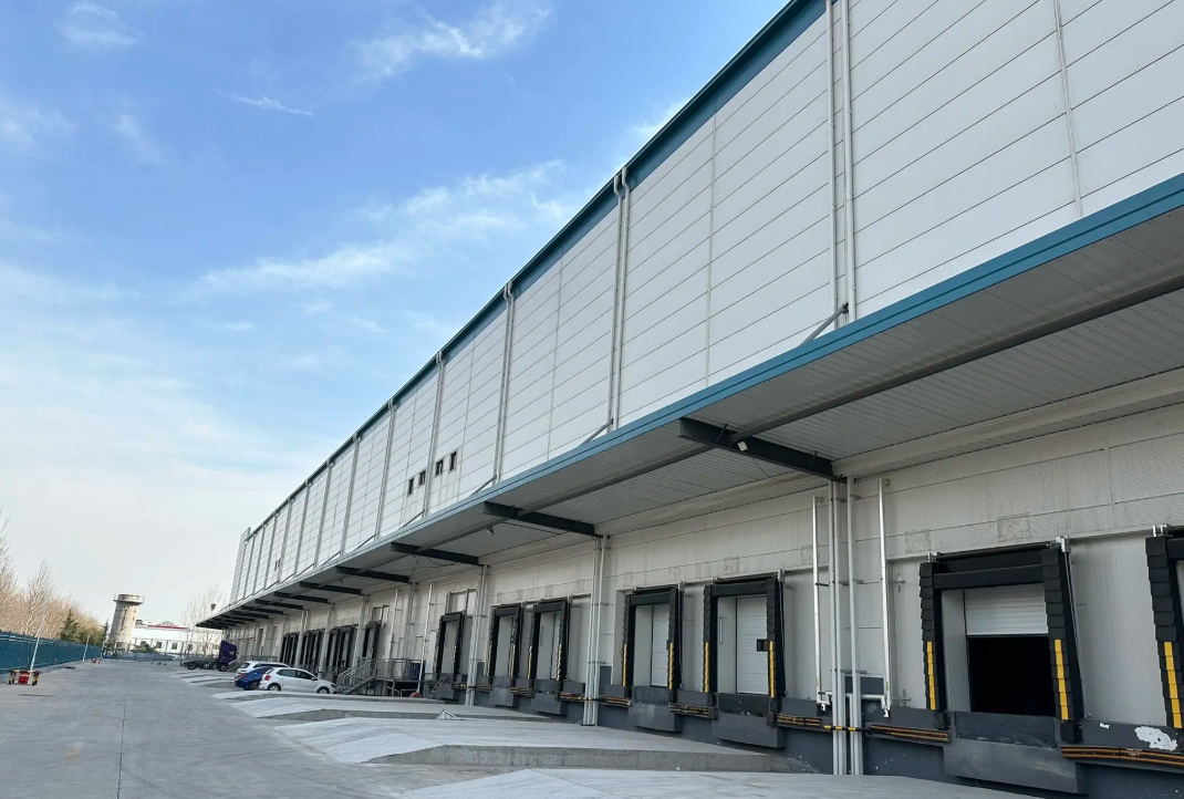
Beyond theoretical calculations, practical execution determines real-world performance.
...
For more detailed information on the load-bearing capacity of steel structures—including an in-depth explanation of the engineering principles—please click here: https://www.meichensteel.com/a/procurement-guides/load-bearing-capacity-of-steel-structures.html